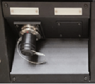
광 커넥트 패널 솔루션
BOP1/FXW/3U
Featureus
1. 3RU Type 45° Safety Angle
2. Include Fusion Splicing of Optical Fiber Tray
3. Installation for FXW Connector (1ea)
4. Aluminium Quality of the Material
Specifications
1. Standard : SMPTE304M
2. Camera Connector : FXW Connector with Connecting Line for 1 Channel
3. General characteristics(Connector)
1) Cable retention force : > 700 N
2) Endurance: Brass+Cr : > 10000 cycles
3) Endurance: Stainless steel : 20000 cycles
4) Drop test : 2 m
5) Shock : 100 g, 10-50 ms
6) Vibration : 7 cycles (20-2000Hz)
7) Standard F2 temperature range : -40° C, +80° C
8) Pre-terminated F2 temperature range : -20° C, +60° C
9) Humidity : up to 95% at 60° C
10) Water resistance : Depth of 1.8 m for 48 hours 11) Corrosion : 48 hours, 5% salt water test
12) Index protection : IP 68
4. Optic-fiber characteristics(Connector)1) Number of contacts : 2
2) Fibre core/cladding ø : single mode 9/125 μm
3) Ferrule bore inside ø : 125 μm
4) Mean insertion loss : 0.10 dB
5. Power characteristics(Connector)
1) Number of contacts : 2
2) Male contact ø : 1.3 mm3) Contact type : crimp
3) Contact type : crimp
4) Conductor AWG min : 18
5) Conductor AWG max : 14
6) Working Voltage max : ≤ 600 V rms
7) Test Voltage : 2250 V rms
8) Rated current : 10 A
9) Contact resistance : < 4 mΩ
10) Shell to shell conductivity : < 5 mΩ
11) Insulation resistance : > 10 to the power of 9 Ω
6. Control characteristics(Connector)
1) Number of contacts : 2
2) Male contact ø : 0.9 mm
3) Contact type : crimp
4) Conductor AWG min : 24
5) Conductor AWG max : 20
6) Working Voltage max : ≤ 42 V rms
7) Test Voltage : 1000 V rms
8) Rated current : 3 A
9) Contact resistance : < 5 mΩ
10) Shell to shell conductivity : < 5 mΩ
11) Insulation resistance : > 10 to the power of 9 Ω
7. Configuration
– Optical fiber closure is free desorption
– Name Plate Include
– Insulation Adapter
– SC Adapter
– Panel Angle : 45° Safety Angle
8. SIZE : 141(W) x 132(H) x 155(D)
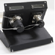
BOP2/FXW/3U
Featureus
1. 3RU Type 45° Safety Angle
2. Include Fusion Splicing of Optical Fiber Tray
3. Installation for FXW Connector (2ea)
4. Aluminium Quality of the Material
Specifications
1. Standard : SMPTE304M
2. Camera Connector : FXW Connector with Connecting Line for 2 Channel
3. General characteristics(Connector)
1) Cable retention force : > 700 N
2) Endurance: Brass+Cr : > 10000 cycles
3) Endurance: Stainless steel : 20000 cycles
4) Drop test : 2 m
5) Shock : 100 g, 10-50 ms
6) Vibration : 7 cycles (20-2000Hz)
7) Standard F2 temperature range : -40° C, +80° C
8) Pre-terminated F2 temperature range : -20° C, +60° C
9) Humidity : up to 95% at 60° C
10) Water resistance : Depth of 1.8 m for 48 hours 11) Corrosion : 48 hours, 5% salt water test
12) Index protection : IP 68
4. Optic-fiber characteristics(Connector)
1) Number of contacts : 2
2) Fibre core/cladding ø : single mode 9/125 μm
3) Ferrule bore inside ø : 125 μm
4) Mean insertion loss : 0.10 dB
5) Return loss (machine polishing) : < -45 dB
5. Power characteristics(Connector)
1) Number of contacts : 2
2) Male contact ø : 1.3 mm
3) Contact type : crimp
4) Conductor AWG min : 18
5) Conductor AWG max : 14
6) Working Voltage max : ≤ 600 V rms
7) Test Voltage : 2250 V rms
8) Rated current : 10 A
9) Contact resistance : < 4 mΩ
10) Shell to shell conductivity : < 5 mΩ
11) Insulation resistance : > 10 to the power of 9 Ω
6. Control characteristics(Connector)
1) Number of contacts : 2
2) Male contact ø : 0.9 mm
3) Contact type : crimp
4) Conductor AWG min : 24
5) Conductor AWG max : 20
6) Working Voltage max : ≤ 42 V rms
7) Test Voltage : 1000 V rms
8) Rated current : 3 A
9) Contact resistance : < 5 mΩ
10) Shell to shell conductivity : < 5 mΩ
11) Insulation resistance : > 10 to the power of 9 Ω
7. Configuration
– Optical fiber closure is free desorption
– Name Plate Include
– Insulation Adapter
– SC Adapter
– Panel Angle : 45° Safety Angle
8. SIZE : 141(W) x 132(H) x 155(D)
Optical Camera Pannel Frame
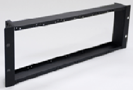
Featureus
1. Installation for BOP Pannel
2. 3RU Rack Size Frame
3. Up to 3 2-channel(BOP2/FXW/3U) panels can be installed
4. Aluminium Quality of the Material
Specifications
1. Installation for BOP Pannel (Max 3ea)
2. SIZE : 197W) x 132(H) x 50(D)
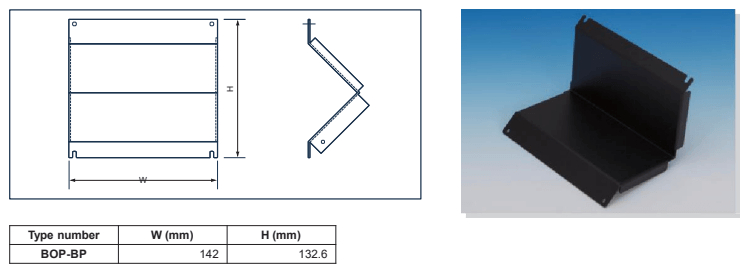
Accessory – Blank Panel
1. Installation for BOP Pannel (Max 3ea)
2. SIZE : 141(W) x 132(H) x 155(D)
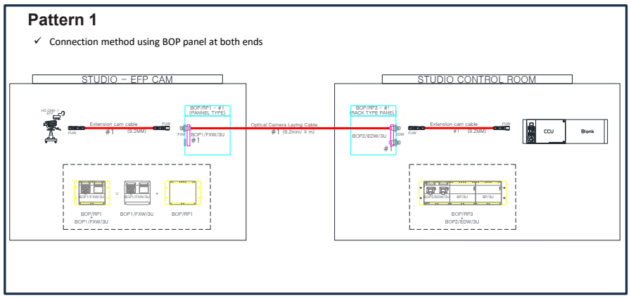
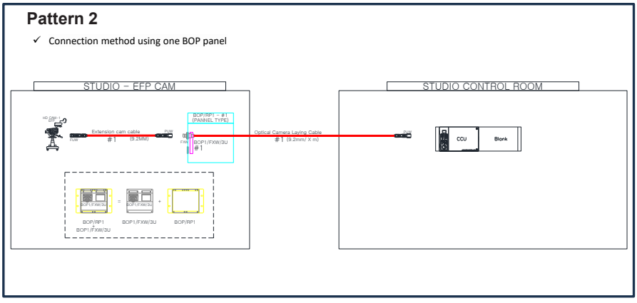
Configuration of Optical Composite Cable for TV Camera
Pattern 1. Connection method using BOP panel at both ends
Pattern 2. Connection method using one BOP panel
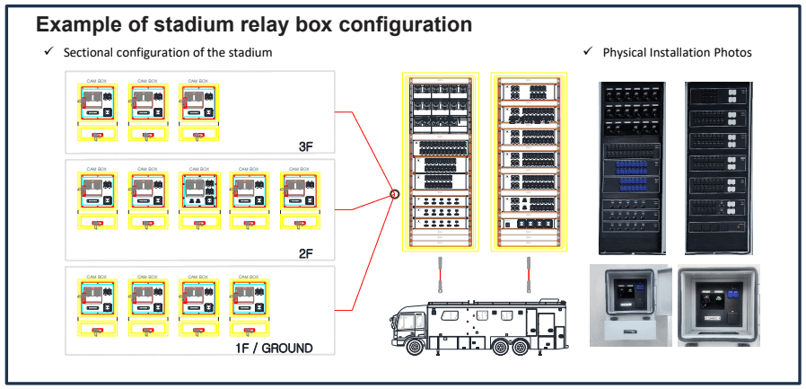
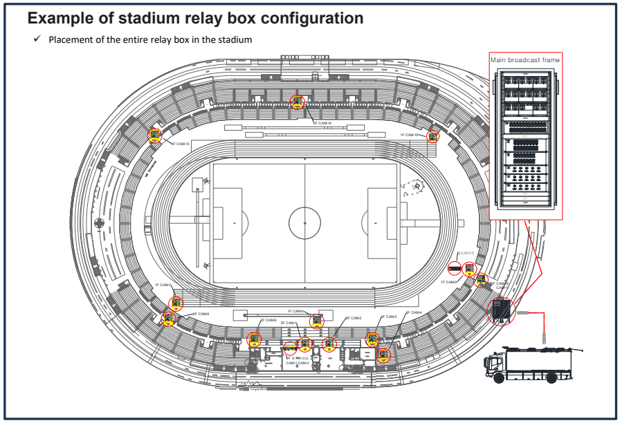
Example of stadium relay box configuration
Placement of the entire relay box in the stadium
Sectional configuration of the stadium